Difference between revisions of "F256 WiFi"
(→Preparing the Feather ESP8266) |
(→Installing the Wi-Fi Module in Your F256) |
||
| Line 122: | Line 122: | ||
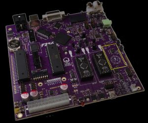
[[File:F256k_unpop_highlight.jpg|thumb|alt=F256k motherboard with wi-fi module position highlighted|Figure 2: F256k motherboard with wi-fi module position highlighted]] | [[File:F256k_unpop_highlight.jpg|thumb|alt=F256k motherboard with wi-fi module position highlighted|Figure 2: F256k motherboard with wi-fi module position highlighted]] | ||
| − | + | # If you did not buy the Feather with the pre-soldered pins, first solder the pins to the Feather board. The pins should be soldered so that the short side of the metal goes through the board of the Feather, and the long end (and the plastic separator) are on the underside of the board. The solder joint should be made on the top side of the board (see figure 3 but ignore some of the less than perfect solder joints). | |
| − | + | # Then it will be time to solder the socket header to the F256 motherboard. The socket header is inserted through the top side of the motherboard and soldered on the bottom side (see figure 4). | |
| − | + | # [Optional but recommended] Use a little isopropyl alcohol to clean any flux residue off the two boards. | |
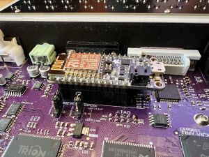
| − | + | # Insert the Feather ESP 8266 wi-fi module into the socket header on the F256 (see figure 5). | |
| − | + | # There are two jumpers next to the wi-fi module. These route the transmit (Tx) and receive (Rx) pins to either the serial port or the wi-fi module. Make sure the jumpers are moved to the "SLIP" positions. You can see this in figure 5 | |
| − | + | # Turn on DIP switches #3 and #4. These tell the kernel that SLIP support should be enabled and that a wi-fi module is installed. | |
| − | |||
| − | |||
| − | |||
| − | |||
| − | |||
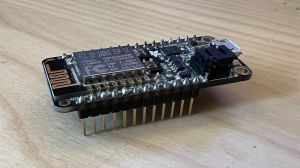
[[File:Feather_soldered.jpg|thumb|alt=Feather ESP8266 with pins soldered|Figure 3: Feather ESP8266 with pins soldered]] | [[File:Feather_soldered.jpg|thumb|alt=Feather ESP8266 with pins soldered|Figure 3: Feather ESP8266 with pins soldered]] | ||
Revision as of 17:34, 28 June 2023
Contents
Foenix F256 Wi-fi HOWTO
Introduction
The Foenix F256 computers were designed to allow for networking either through the serial port or through an optional wi-fi module. The TinyCore MicroKernel installed by default includes support for networking using SLIP (Serial Line Internet Protocol). While it is possible to use SLIP through the RS-232 serial port on the F256k and F256jr, both computers include solder pads that can be used to install an ESP8266 board to serve as a SLIP wi-fi router. This document will cover the process of configuring and installing such a wi-fi module on your Foenix F256.
WARNING: The process described here requires some technical skills. It will be necessary to solder sockets to the F256 motherboard, which, if not done properly, could damage the board. Therefore, this process should only be attempted by someone comfortable soldering electronics onto PCBs. Similarly, some steps in setting up the wi-fi router can currently only be done on a Linux installation, so some experience with Linux and setting up software packages on Linux will be needed.
Supplies Needed
- F256 Motherboard
- Either the F256jr mini-itx motherboard or the F256k motherboard will work.
- Feather Huzzah with ESP8266
- This board will be wi-fi module when the correct firmware is installed. It is available from Adafruit (product link), either with or without the pins pre-soldered. While the firmware will run on other ESP8266 boards, the solder pads on the F256 motherboards are designed for the Feather board from Adafruit. Be sure to order the Feather with the header pins (not with the "stacking headers"), although the correct header pins are readily available from several suppliers, as they are commonly used with Arduino projects (single row, 0.1 inch (2.5mm) spacing).
- Header Sockets
- Single row, 0.1 inch (2.5 mm) spacing. These are commonly available from many suppliers, but Adafruit have a kit including the correct sized headers (product link).
- Soldering Supplies
- Soldering iron suitable for through-hole soldering, decent solder, flux, and cleaning supplies to remove flux residue.
- USB Cable
- A to B Micro : This cable will be used to connect your Feather ESP8266 to the computer you will use to install and configure the firmware.
Software Needed
- ESP_SLIP_ROUTER
- The firmware to install on the ESP8266 to turn it into a SLIP/WiFi router. GitHub Repository
- Linux
- While installation of the firmware on the ESP8266 can be done in Linux, Windows, or MacOS X, the configuration step seems to be possible only using a Linux install. Currently, configuration of the wi-fi router once the firmware is installed can only be done through a SLIP connection, but Windows and MacOS X do not support SLIP networking. An installation on a Raspberry Pi should be fine.
- Python 3
- Needed by the esptool.py for installing firmware on the ESP8266.
- PySerial
- The Python package that provides serial port access for esptool.py.
- esptool.py
- Tool used to install firmware on the ESP8266. GitHub Repository
- Net Tools
- A package for Linux that includes the
slattachcommand, used to configure the wi-fi router. The correct link will depend on your Linux distribution, but it may already be installed.
Preparing the Feather ESP8266
This process is a bit involved on the software side. There are really just two main tasks that need to happen:
1. Installing the ESP_SLIP_FIRMWARE
2. Configure the ESP8266 for Your Network
However, both of these tasks require that the correct software and libraries are installed on your system. The first task can be done using Windows, Linux, or MacOS X. The second task can only be done using a Linux install at this time. The example commands below are shown for Linux, and in particular the Ubuntu distribution.
Installation Prerequisites
If you are currently using the FoenixMgr Python script to work with your F256's debug port, then you already have the prerequisites installed and can skip this section. Otherwise, you will need to make sure you have Python 3 installed, set as your default version of Python, PIP installed, PySerial installed, and the Net Tools package installed:
1. Install Python 3
sudo apt install python3
sudo apt install python-is-python3
2. Install PIP
sudo apt install pip
3. Install PySerial
python pip install pyserial
4. Install Net Tools
This will vary with each Linux distribution. Sometimes this package is installed by default.
Installing the ESP_SLIP_ROUTER Firmware
Use the USB cable to connect the Feather ESP8266 to your computer and make a note of the device or COM port the Feather will used. Now, the esptool.py script may be used to install the ESP_SLIP_ROUTER firmware. The ESP_SLIP_ROUTER repository includes two binary files in the firmware directory that need to be installed.
esptool.py --port {device} write_flash -fs 8MB 0x00000 {path}/0x00000.bin 0x10000 {path}/0x10000.bin
Substitute the path to the USB serial device for your ESP8266 (likely /dev/ttyUSB0 or something similar on Linux, or some COM device on Windows) for {device} and the path to the ESP_SLIP_ROUTER's firmware directory for {path}.
The activity light on the Feather should flash for a bit. Once that is complete, the firmware should be installed.
NOTE: you may get an error message about access to your device on Linux. It is common for Linux distributions to lock USB device access to a special group. You can either add your account to that group, or for a quick and dirty solution add read and write access to all users—for example:
sudo chmod a+rw /dev/ttyUSB0
Configuring the ESP8266 Router for Your Network
To configure the router, you will need to make a SLIP connection over the USB cable and use the router's console to set the SSID and password of the wi-fi network it is to use. Unfortunately, there does not seem to be any SLIP support in Windows or MacOS X anymore. This is why a Linux install is needed.
To make this connection, you must first issue some commands in Linux to create a SLIP tunnel over the USB cable to the router and to assign it a local IP address so you can connect (assuming the Feather is on /dev/ttyUSB0. Substitute the correct device path, if it is different.):
sudo slattach -L -p slip -s 115200 /dev/ttyUSB0 &
sudo ifconfig sl0 192.168.240.2 pointopoint 192.168.240.1 up mtu 1500
Once that has been done, you can use telnet to connect to the router's console:
telnet 192.168.240.1 7777
At this point, you should see a prompt from the router's console. Enter the commends to set the SSID, set the password, and set the router to use an access point:
CMD>set ssid {your_ssid}
CMD>set password {your_pw}
CMD>set use_ap 0
CMD>save
CMD>reset
At this point, the wi-fi module should be ready to install in your F256.
Installing the Wi-Fi Module in Your F256
The next step is to actually install the wi-fi module onto the F256 motherboard, and this step will require some soldering. If you look at the motherboard, you will see two rows of unpopulated pads. These pads are for the wi-fi module. You will need to solder socket headers to those pads, and then insert the Feather ESP8266 wi-fi module board into the headers.
- If you did not buy the Feather with the pre-soldered pins, first solder the pins to the Feather board. The pins should be soldered so that the short side of the metal goes through the board of the Feather, and the long end (and the plastic separator) are on the underside of the board. The solder joint should be made on the top side of the board (see figure 3 but ignore some of the less than perfect solder joints).
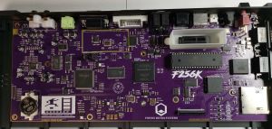
- Then it will be time to solder the socket header to the F256 motherboard. The socket header is inserted through the top side of the motherboard and soldered on the bottom side (see figure 4).
- [Optional but recommended] Use a little isopropyl alcohol to clean any flux residue off the two boards.
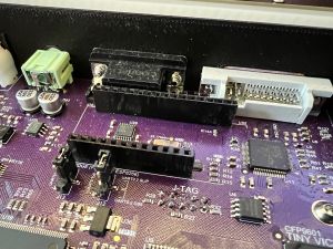
- Insert the Feather ESP 8266 wi-fi module into the socket header on the F256 (see figure 5).
- There are two jumpers next to the wi-fi module. These route the transmit (Tx) and receive (Rx) pins to either the serial port or the wi-fi module. Make sure the jumpers are moved to the "SLIP" positions. You can see this in figure 5
- Turn on DIP switches #3 and #4. These tell the kernel that SLIP support should be enabled and that a wi-fi module is installed.
