Difference between revisions of "FMX Errata"
Jump to navigation
Jump to search
(→Errata: Known Issues with the Board or Firmware) |
(→Errata: Known Issues with the Board or Firmware) |
||
| Line 10: | Line 10: | ||
[[File:FMX Floppy Screw.jpg|600px]] | [[File:FMX Floppy Screw.jpg|600px]] | ||
| + | |||
| + | ; Errata 3---Floppy Cable Density Signal (11/04/2020) | ||
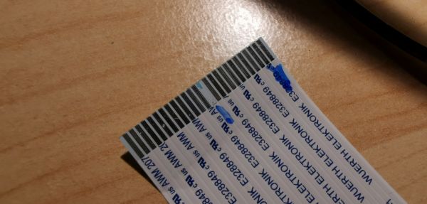
| + | : Pin 13 on the floppy drive connector cable was grounded on the board, which prevents the floppy drive from being able to use 2.0MB unformatted (1.44MB formatted) floppy disks. There are two simple solutions, both involving disconnecting that pin. The trace can be cut on the board near the floppy drive connector, or the conductor can be remove from the floppy drive ribbon cable. | ||
| + | |||
| + | [[File:FMX Floppy Cable Errata.jpg|600px]] | ||
Revision as of 07:20, 11 April 2020
Errata: Known Issues with the Board or Firmware
- Errata 1---MIDI IN Port Pin Inversion (25/03/2020)
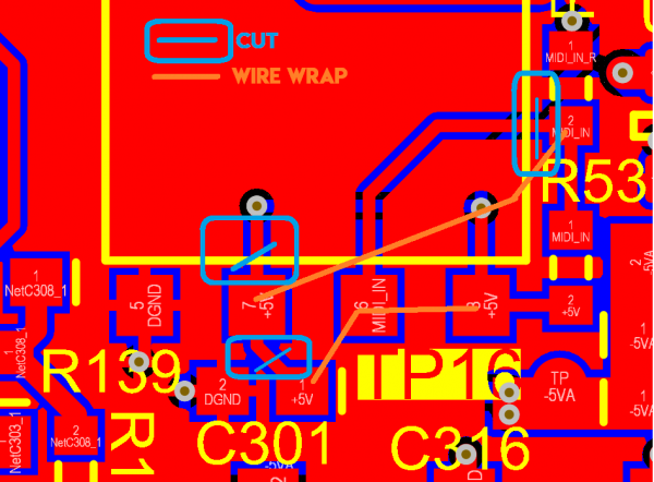
- Pins 6 and 7 on the MIDI IN port of the RevC4A and RevC4B are reversed. Plugging a device into the MIDI IN port will result in a short from +5V to ground. The board can be fixed by cutting three traces (marked in blue in the diagram below), and then soldering two jumper wires (shown in orange). As an alternative if there is no desire to use MIDI IN, the pin connected to pad 7 in the diagram below could be lifted from the pad to prevent a short.
- Errata 2---Floppy Mount Screw is Too Long (11/04/2020)
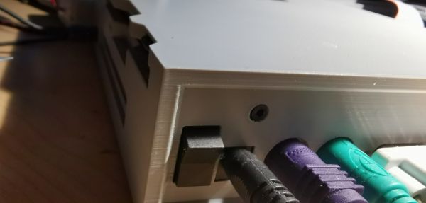
- The screw close to the power switch, which is used to secure the floppy drive to the case is too long and interferes with the drive's internal tray that holds the disk in place. This prevents the disk from sitting correctly and interferes with the drive's ability to read the disk. The problem can be solved by loosening the scree 2 or 3 turns.
- Errata 3---Floppy Cable Density Signal (11/04/2020)
- Pin 13 on the floppy drive connector cable was grounded on the board, which prevents the floppy drive from being able to use 2.0MB unformatted (1.44MB formatted) floppy disks. There are two simple solutions, both involving disconnecting that pin. The trace can be cut on the board near the floppy drive connector, or the conductor can be remove from the floppy drive ribbon cable.


